Friday, June 16, 2023

Reverse engineering wireless water meter network - Part 2

Hello again!

tl;dr - This is How I "hacked" - Identified, Isolated, demodulate, decode and analyzed a wireless water meter sensor network (Version 2 as mentioned here) that works on 4-fsk modulation with CC1120 (or similar) chip, using SDR, this series will include as much information as one could use to get ideas for his/her own projects :)

I Would try not to include information that is numerously available in other places, modulation, demod, how to identify signals and what are the different techniques, go to youtube/google for that, U don't need me :)

Coming from part 1

Before I could even finish analyzing the external transmitters that were attached to the plain meters completely, the water company have replaced the areas water meter (although the meters were used for only something 2 years and were working properly).

New Setup

Now they detached all of the external transmitters (left them onsite, unused, free electronics $$$ !! :P) 

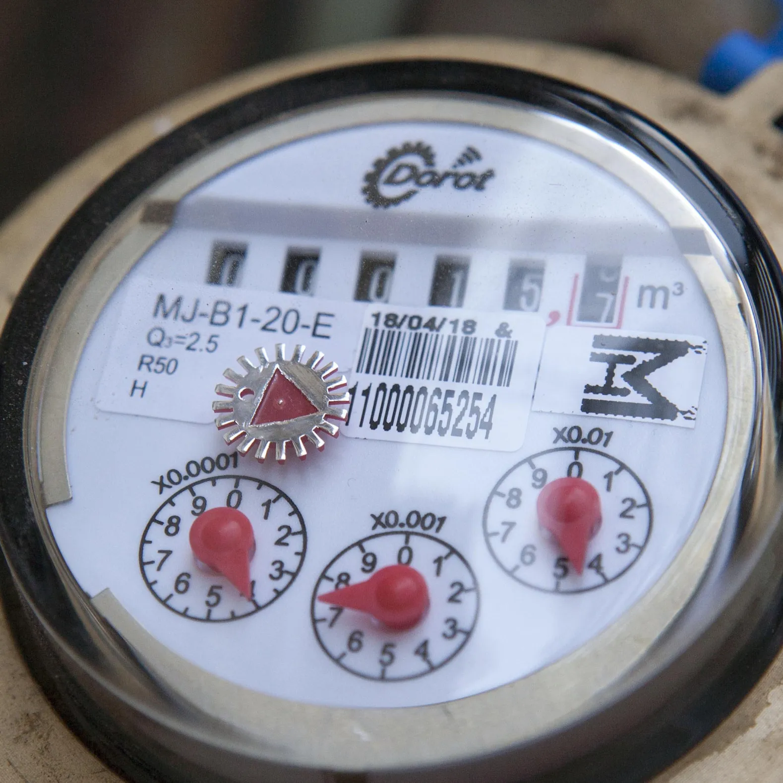
Looking online I found that these types of meters have their AMR transmitter embedded as a part of the mechanical meter itself, housed in the same casing. This was the same company that made the earlier transmitters, partnering up with a company that makes these water meters.

I Asked the vendor for some information, the only data I received that it is still possible to trigger a transmission with a magnet, and it's virtually the same solution (Hint: it's not).

Also, whenever it was "Shabbat" one could see a blinking LED from the housing of the meter, I guess stating that the meter has entered Shabbat mode and it's Kosher so turning on the home faucet, won't violate the Shabbat, to the ones which this is important to them.

I Could also find documentation regarding that this meter is "Kosher" from The Technological Institute of Halacha (הלכה) explaining this feature.

Getting techy: V2 Meters (new, embedded, 4FSK)

Recording

I've tried using the magnets that I have - but this proved not to work, Couldn't find how to trigger it, I Eventually opted for a stronger magnet and found where it needed to be placed in order for it to trigger. When it does, LED turns on for a few seconds.

Tried the frequency I know from the earlier generation - Nothing. I Asked them for the frequency and they responded with 465Mhz, But I Couldn't see any traffic corresponds with my triggering. It seems like they were off in their frequency?

I've again scoured the 300-400 range manually, painfully, slowly. and found that something happens around 433Mhz.

Analysis:

This is how it looked after one trigger, in an amplitude-view


And this is how it looked on a frequency view/waterfall (time:x freq: y)


OMG! Are they using some kind of Frequency Hopping Spread Spectrum? I Wondered... This would be harder then I thought.

______________

Let's anyway try to take a look inside one of these, Now since Universal Radio Hacker is available (as this wasn't available at my first research into the older meters), it made this analysis INSANLY easier. This is after some filtering, and zooming in the signal


At first, this looked strange to me, a digital signal shouldn't look like that. I Also saw these signals around the 465Mhz in my home area (not directly triggering the meter) and at the beginning thought they are some noisy signals.
These signals just captured in my area on 465.65 Mhz seem to match to what I'd expect from such transmission:
  • Short, narrow bursts
  • Varying degree of quality and noise
  • Varying degree of RSSI (i.e. stronger (closer) and weaker (further away) signals, as these meters are all over the place.
Looking online for FHSS information, It looks like synchronization pattern should not appear on each of the channels. also there's quite a delay between the different burst.
In addition to that, the spontaneous transmission on the frequency I received from the vendor did not contain this pattern.

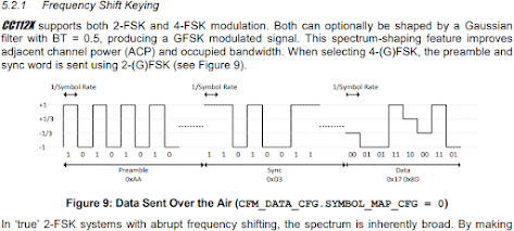
When digging for information about the device, I also saw one of the commercial names for the device. So after a lot of effort googling and researching whatever I can find online I found this ! and it did made some sense. This is a 4FSK signal!

I Have tried to see how can I get all the channels back to baseband, thinking I probably need the information which is spread out over the different channels. That was time consuming to do in a pipeline manner, but let's test my theory with the minimal effort needed, does this signal make any sense? what does it mean? can I even start to analyze the data inside using the different meters/different bursts? as a foothold for understanding the traffic?

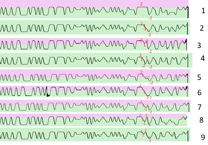
Let's "eyeball" if the data is similar/different within these multiple bursts.
I took each one of these bursts and switched to a frequency view after filtering. I also tried to align the different burst so I can see if there is any meaning
I tried to manually align and compare the different burst and also map where are also the same and where do they divert from each-other

All of these samples were taken from 1 meter in 1 specific occurrence when I triggered the meter only once When water did not flow through it, So information should relatively stay static.
We might expect to see in the transmission values such as:
  • Sender or meter identifier - no change
  • As demonstrated in 1st generation of the meter, Send counter - not sure, is this one transmission or multiple ones? - if multiple, so we'd expect for each burst bo be +1 from the last one
  • Water reading - no change
  • Time? - if exists depending on the resolution and the specific capture time
  • Checksum - It's a wireless protocol, there is probably some kind of error correction/detection mechanism. Checksum or a CRC would expect to change noticeably if the underlying data is changed (such as the parameters above).
So what do we see here, mostly the same symbols, somewhat a bit different in the middle and in the end there are more changes.
I Manually demodulated the waveform into the 4 different symbols (On the rf spectrum I used 3 1 -1 -3; And on the symbol mapping into bits I've used ABCD as I didn't want to hint myself that A was necessarily 11 etc) and compared each consecutive ones.

The first symbols that is changing across all of the transmission I identified, changes with every transmission (the unmarked one ~mid transmission). there also multiple symbols that change nearer the end of the burst, leave that for now, let's stick to the simple one.

So what if it's a counter that is +1 in each of the bursts? what would we expect to see without any knowledge of the encoding or symbol in such case?

Since it's a 4 fsk signal, each symbol represents 2 bits. so 1 symbol (Symbol `0`) can be the value from 0-3, Where after 3, the higher-value symbol should flip also (Symbol `1`) .
Luckily, we see just this behavior. We don't know exactly in which value do we start on (0-3) but we would expect for the higher-order symbol 1 to change every 4 bursts, and then necessarily 4 more changes to the lower-value symbol before higher symbol changes again. (Also applies 4^2 for flips between symbol [2] and symbol [3]). 
If this is too confusing, just think about it as a counter with 2 digits on base 4; but let's look at this base with Alphanumeric chars. A counter would be for example AA AB AC AD BA BB BC BD... etc
If we don't know which of the 2 are the lower value - we could tell by that that it's the one that changes more frequent. In addition, to know what is the lowest value among a set of symbols (i.e. what can be considered a value of 0) we can check if we see 2 simultaneous changes within this counter as the higher value would increment by 1 and the lower value would "zero out", 


So, after symbol [0](lower value) and symbols [1](higher value) both flips, we can assume that symbol [0] conveys the value "00". And so we have the symbol mapping. I did this process for also the higher symbol, symbol [1]. And it seems like there is also a 3rd symbol for the counter, but that requires 64 bursts in order to see, which is cumbersome... 


So now I have the mapping table for 2 out of, possibly 4 variations of translation.
I wrote multiple scripts of trying to brute force the other patterns, but I could still not find my meter id in the result or have something that makes sense counter-wise.

is the data encoded or encrypted in some other way?

 "Remote" Hardware reverse-engineering

After failing to understand the modulation, or at least the translation of the symbols into bits (which may also be not possible, if this data is encrypted). I've tried turning to other ways (again) what is being used to transmit this data, also, why it starts of with a symbols -3,+3 that looks like 2-fsk and only in some point of the transmission goes to "real" 4-level fsk?

I cannot tear down the hardware, but I do have the fcc documentation.
Which chip is being used to transmit this?

Fuzzy photos of the rf chip from the fcc documentation

We know
* Frequency ("sub ghz")
* Symbol rate (Hence, also baud-rate)
* Modulation
* Possibly, preamble and sync pattern
* Packaging of the IC can be extrapolated by the pictures of the PCB, from the pictures in the FCC docs
* Low power
* Narrow-band (where bit rate>=bandwidth, in other words "more frequency changes is compressed into a narrow-er rf spectrum; Like recording LP on a video cassette )

I Have reduced the number of options to 2 vendors, Analog Devices ICs and Texas Instrument ICs judging by this christianistic alongside the number of pins I counted from the ICs photo.

Now, if we were to assume both preamble and sync pattern are 2fsk in this part, preamble would value would be `101010...10` sync would be around 32 bits I counted manually. I decoded the values assuming -3 as 0 and 3 as 1. into Binary: 10010011000010110101000111011110; Hex(First bit received MSB) 93 0b 51 de (0x930b51de).
This wasn't on first shot, I wasn't sure about the size of the preamble and the sync byte, but assuming preamble is repetitive and sync does not contain +1 -1 symbols and should conform to some round-binary number so margin is not to big to look all possible combinations online for the sync word.

Guess what I've found, the sync word maps to multiple example codes online, for Texas Instruments family of transmitters. A special candidate was the CC1120; which Datasheet say "1.2 Applications: ... Wireless Metering and Wireless Smart Grid (AMR and AMI)" - Jackpot :) 

Drilling further into the CC112x User guide proved my observations correct. in 4-fsk mode, the preamble and sync word pretend to be 2fsk (I.E. No +1 -1 symbols, only -3 +3). Following sync, transmission moves over to the packet payload part which is 4-fsk.

Symbol mapping

Now we have a bit more clarity of what we're doing and that I'm on the right path.
What are the symbols inside this data map into? The datasheet states there is no "data dependent mapping", They have just all 4 possible combinations


This is where a long guessing game started, it took quite a while, I even thought the information is cyclic-encrypted with a 4 symbol key, or something. but after writing some scripts that would do some brute-forcing I couldn't find anything that made sense.

Universal Radio Hacker to the rescue again!

In one moment, I remembered when looking into URH they have an internal Decoding tool in there was something I recalled to be related to CCxxxx something. 

This is basically boils done to XORing the underlying data with a predefined key the CC1120 also supports this feature.

The data and example in the following step might be somewhat wrong or misleading, the research was done a long time ago and I'm just now writing this blog post. The steps and concept mentioned were used in this research just not necessarily the specific data that I'm writing here or the order of the things I've attempted


First I tried using Universal Radio Hacker to extract the data, but that never worked reliably, as each of the transmitter has a slight CFO, URH does not account for that; Also even after re-centering for one specific meter I could never get a reliable slicing of the bits.

I successfully made a GRC flowgraph that was able to extract the symbols from just one capture of one meter that was captured with a magnet, assumed that the mapping is the first one in the datasheet. and extracted the part that comes just after the preamble:
F0 EA ~~ DA 8B 83 833324EA7F51  (some data censored with ~)

For data whitening the key starts with FFE11F9AED853324EA...
When decoded it looks something like this:
0F 0B ~~ 40 66 06 000000...xxxx

- So again - looks like we're on the right path! all of these different symbols, when XORed with the right value, zeroes out if were to do just random XOR or something that wouldn't make sense, what are the chances of the data accidently zeroing out?.

Now, with a little bit of trial and error I've reached to a conclusion that xxxx is a checksum of all the information before that. Why I tried that? well look in the photos above of multiple such transmissions visible and aligned together. It's possible that a "slight" change in the payload, would lead to a big change in the checksum (which is presumed to be near the end). This hits us that the last part of the transmission is a checksum of some sort.

The meaning of life (ahh.. data)

Now we have what looks like demodulated, decoded, unencrypted data.
We need to start actually understanding it.
This is where I thought the knowledge from the old gen meters would help - Totally didn't, trying out both manually and the excel method didn't yield anything; As with the previous generation. I expected to see the meter id in the transmission - But failed time after time.

I totally missed that, but can you see a hint in this picture for the way data is encoded into the payload?

Assuming u did missed that, as I did too, eventually I accidently decoded the different bytes into decimal, instead of hex.
Suddenly sublime highlighted me the top-value of the meter id within the same file matches the payload.

I call it "decimally-numerically encoded"! hell - Who thought of this grate idea?
... And please let's never hear this term again...
What's that - It's like BCD coding for 3 decimal digits into a byte value, you can represent 3 10-base digits as long as they're value don't go above 255, this is why you will never find a meter id ending with higher then xxxxxxx255 ! (also applies for higher tribbles ("three nibbles")).

This was later a straightforward process the packet recorded in the magnet proved to contain, only, length, meter id along with an additional unknown byte, lots of zeros and a checksum.

Going municipal 

Well there is no other data to analyze in the frame recorded in the magnet. So I switched over to the other frequency (465mhz) to try to pick up the neighborhood meters. 

I had lots of bad frames, by this can be verified by a checksum so I don't need to guess which ones were received and parsed correctly.
in the wild, we have several sizes of frames, they aren't always this small. 

Applying what I've learned above to the framed received correctly worked I could see the transmitting meter Id; but the Id also appeared, sometimes in a frame following it, in a different location.
Judging that that the received RSSI was different, I was thinking this is a 2 way system, where the meter sends data to the base station and the base station returns data to the meter (most of the time, something like a timestamp). Awesome.

I Have used a setup with an SDR connected to a DVB-T Antenna on top of my building - which basically say, yes, I can receive lots of the area.

From here this was fairly easy but long iterative process, where I was able to understand the meaning of the data in this different frame types as expressed in the python code in the github repository.

Conclusion

* OMG - That worked!
* Hell - It took ages to figure everything out
* When writing on this in this blog post, everything seems fast and efficient; That's not the case, sometime there was no any progress for weeks. Recording in the residential area with the rooftop antenna needed to occur overnight as I'm looking for specific meters and they rarely transmit. overall I'd estimate this took me around 1 year overall (off course I sometime have life, family and job as well so consider that)
* Some thigs are still technical issues: 
  * I Don't actually know how to demodulate 4-fsk, I tried lots of different things until something worked, 60% of the received transmissions. - Please consider contributing to the repository if u know anything in SDR :)
* It's not really clear why the with a magnet, the transmitter sends data on 433mhz instead of it's original frequency. 

Code / Repository / Research end results are in the github repo: https://github.com/hllhll/MLL-AMR-SDR

Wednesday, September 22, 2021

Reverse engineering wireless water meter network - Part 1

Hello,

tl;dr - This is How I "hacked" - Identified, Isolated, demodulate, decode and analyzed a wireless water meter sensor network (Version 2 as mentioned here) that works on 4-fsk modulation with CC1120 (or similar) chip, using SDR, this series will include as much information as one could use to get ideas for his/her own projects :)

I Would try not to include information that is numerously available in other places, modulation, demod, how to identify signals and what are the different techniques, go to youtube/google for that, U don't need me :)

This posts would be divided to - I don't yet know how many parts, let's just start

BTW - Sorry for the image sizes, couldn't resize them without loosing quality 

Chapter 1 -  Circumstantial Background

DISCLOSURE: This chapter only presents the subject as I see it and reflect only, my totally biased opinion.

Local water companies in the past were part of the municipality water payments used to go directly though them and additional "water supplier" was redundant 

However, a while back some folks, that I can only guess wanted to increase cohesion and get some free meals, managed to pass a law setting up tens of privately-owned, locally-monopoly companies, in a very very small country to allocate, manage and sell the water to everyone under the national infrastructure.

As, expected the prices of water shoot up and this created a whole lot of jobs that there wasn't any need for them in the first place, with the bloated prices and now that's a whole pile of companies that needs to make money, some more, let's say "technological opportunities". Or in other words, how to get this money, from the hands of civilians or somehow-regulated company into the hands of private contractors.

One such methods is the use of an Automated Water Metering system, or AMR.

Why do I say this in this form? well:
  • You can read the municipally RFQ (Michraz?) In there you could see that, usually they narrow the eligible companies very much, preserving the cartel in this area.
  • You can see that they often argue at court trying really hard to get a piece of the pie for another one. Prevailing a contract in a certain municipality usually guarantees contracts for years ahead (see next bullet)
  • The all use different, proprietary, custom technologies to implement their solutions. Switching between them, is a hassle, and not I said that, a 3rd party did...

Chapter 2 - The problem

AMR Solution means water suppliers can collect data in some periodic interval and can even provide them to the costumers. However, in my city, data is not exposed to the costumer by any reasonable means. Sure you can call the water company, wait in line and then beg to get your AMR reading. but that's not the way this should be in the 3rd millennium, especially, when the data is already existing and there, you just need to make it accessible.

So I can't get a recent updated meter reading. In addition the use of this system should help the provider identify leakages and thus they could Text the consumer - Although both the building and on my personal water meter I had a few of these, we never got any SMS as they say they would, the water just kept on flowing.

So,
Can we get our water meter readings without the help of the supplier?

Chapter 3 - Background & Method

Technical background

I Don't want to invest in this too much, you can read online, basically anything goes depending on the implementation. The goal is to get the reading from the meter to a central location, either every dT time, request response with static basesstations or even driving with a broadcasting/receiving antenna, 3g networks, LORA, BLE, whatever, I guess there are hundreds of different methods out there.

They are usually battery operated, and thus need to be low power, some might have a local: leakage detection algorithm, temper detection function, "halted meter" detection algorithm, low battery, etc. This data should also somehow needed to be transferred to the either basestation or central location.

Method

The idea is to catch these transmitting in-air and decoded them; Whenever the utility company gets the reading, I would get it too. Using some sort of an SDR with a raspberry pie setup hooked up to some antenna.

Chapter 4 - Getting techy: V1 Meters (older, 2FSK)

Okay so my local setup was as follows:
a bunch of a classical, "dumb" meters were connected with wires into some enclosed device nearby which had the manufacturer name stamped on it.
There is also some 5 digit id with a barcode on the device, which I guess is the transmitter id.

Recording

For those of you that already know all the tricks for RF hacking - Yes, there is and was a lot of material from the FCC on this kind of devices, although frequency band may change, overall architecture would probably not. But apparently, that's not enough these days.

The FCC Documentation stated that the transmitter can be triggered to send with a magnet, setting up my SDR with relatively low gain and being closely allowed my just to brute-force the range and see were I see a burst that corresponds with my magnet tap.

Demodulation

Following NCC Groups guide was very helpful, at first at least. This part was done long ago, so back then- Universal Radio Hacker Did not exist, yet. Trying out millions of ways to recover a clock from the signal was virtually impossible with my tiny understanding of DSP.

I Could not get any reasonable results, so I turned over to GNURadio mailing lists asking what I'm doing wrong. Andy Walls from the mailing list, helped me figure that one out, so demodulating FSK, TWICE, proved to get me the underlaying bits. they could later be sliced with Michel Ossman's Whole Packet Clock Recovery (WPCR) script

Decoding

I Have managed to get my hands on a MS-DOS Binary that is part of this solution, investing heavily in RE & IDA proved me that the decoding is not done in this binary maybe this is offloaded in some embedded hardware at the receiver side. But, it did proved helpful to find out more features that might be lurking in the transmission . For instance, each transmission has some kind of counter attached to it so the receiver could identify dropped frames,
With the bitstream in place - Trying to find the meter id or transmission number or the reading that is on the physical meter proved to be impossible. NRZ, RZ, Inverted non inverted, reversed, aligned to 8 bit 7.
Nothing. I couldn't find any meaning in the bitstream, although it did seem to have some pattern.

Working on multiple transmitters

Since this is a dense residential area, there were multiple of these units, each with it's own stamped-id, I thought I could get multiple recordings and check against the transmitter id. I still couldn't find any match between the ID and the recovered bits.
Eventually, I started to try and identify MANUALLY if changes in certain bits of the meter id changed somewhere in the bitstream, consistently. this was virtually impossible to do it by hand,

And then... It struct me...

Chapter 6 - Identifying data with excel spreadsheet

..."Wait just a moment, what am I trying to do?
- Well, I'm trying to find a CORROLATION between each of the bits of the known id, to anywhere in the bitstream.
- Hell, why shouldn't I do correlation with excel?"
I thought to myself

Well, you can,
just set up the known data with the unknown data side-by side 


I have removed the most valuable bits that are the same across all IDs (on the left) and the starting bits (I.E. 1st bit received by the receiver) that are the same across all captured data, as it would not produce any meaningful results.
PEARSON function allowed me to calculate correlation between different columns, each bit if the id(s) with each beat in the captured data(s), with some excel magic, we got a table with the correlation data.


Data with alternating hops 

There are some:
  •  1s-Meaning where's a bit value with value X on the id, it correlates to bit value X on the capture. And
  • -1s - Meaning where's a bit value with value X on the id, it correlates to bit value !X on the capture. 
After filtering from it, a pattern emerged, the transmitter id IS in the capture, in "bit hops" of 16 and 20 bits, alternating. This proved to be 100% reliable.

So there might be some shift register or some encoding that messes with the data, I've decided to call it a "field" and it should start with a bit number, and then hop according to this pattern.
I checked out the other fields, and one of them proved to contain the transmission counter :)
You can check out the script for that in this github-repo/ticket where I solved this guy's issues.

Part 1 Conclusion

It took A WHOLE LOT OF TIME AND EFFORT but this project was driving me crazy, I wanted desperately to solve it, and I eventually did, but until I've done so, and as mentioned on chapter 1 - They dont care pouring a whole lot of money, the meters were replaced by a newer generation
Well... Figuring this out would help me work out the new generation (This was the same vendor), right?
I Couldn't be more wrong...

Wednesday, October 12, 2016

SD Card slave controller emulation

As hackers, we sometimes need to intercept and fiddle various communications; Such as HTTP (using proxy) raw TCP (for example EchoMirage etc).

When auditing smart endpoints system for vulnerabilities, we need to take it to the next level. If this is testing actual hardware using some SPI MiTM or other example such as tools that enables USB Interception such as the FaceDancer or USBProxy.

Where I'm working I was lucky to use both FaceDancer and USBProxy to test USB implementation of an end system.
The tested device also had a native SD Card slot. When researching I found there is no such framework to test lower level implementation of SD Card controller/Driver or even for faults in the end application layer.

And thus became my conquest for implementing a

SD Card Slave Controller

Lets put a few things aside
  • I know a bit about hardware but don't know anything about hardware design
  • Don't have a clue about HDL/Verilog/VHDL
  • Don't know if I'm going the right way or if it's going to work
  • It will, however, be very interesting and I'd probably learn a TON in the process.

Why hardware

Typical SD Card controllers fires up the CLK in an SD bus at ~500kbps minimum. Hance, sampling rate should be at least 1Mbps; While also need to parse the protocol, which does requires more processing. I Even started implementing (bitbang-ing) the protocol on a 80Mhz Cortex M4F I had lying around. Well, Either I did something wrong or it is still too slow to parse the SD frames correctly.

But I know SD Card also support SPI, Why not to use available SPI-Slave?

It is true, All SD-Spec-Confirming SD cards should support SPI mode; BUT, The cards start up in native SD mode, 1 Data bit(citation needed). While we can choose to work with SPI mode if we are the READER, it is not us to decide that if we are the CARD, plus, since native SD is faster, and all cards should support it, my informed guess say that no high speed card reader actually put the SD into SPI mode. this also goes for other basic properties such as starting baudrate.
However, other features of the protocol (Supported maximum speed, number of data lines, etc) are negotiable with the reader.

Physical layer

Well, I have some access to skilled individuals who were able to set me up with 2 "platform" (basically, just wiring that I can connect to the proper equipment) to mess around with.

  1. First, SD/Micro Card adapter are easily taken apart, then with some skill one can extract all pins to external headers
    <pic>
  2. There are such micro sd card extension cables, again, with a skilled hand this could be made in to fully blown wiring to do a MiTM for the bus or sniffing via logic or other.

How will it blend?

So here are a couple of assumptions i'm using:

  • Implementing only in software is probably hard, or, will require some really fast processor
    • Thus at least some level of protocol implementation would be in hardware, In a similar fashion in which today's sd cards implement the bus protocol using a hardware core.
    • So the most logical way is to implement something on a FPGA using HDL
  • In the end there should be some kind of CPU, after some research, one of the possibilities of FPGA is the Xilinx seriues, Maybe the Papilio board.
    • The Xilinx FPGA has a `Arduino-like` implementation on the FPGA (ZPUino),
    • We can actually build our own cores and connect it to the arduino-ish proccessor!
      • VERY COOL.
  • How can we connect out core to the Wishbone bus (the on-chip periphial bus used by ZPUino)
    • We have a Wishbone IP Core generator to connect our HDL core implementation to the wishbone bus; No need to implement wishbone - You supply this tool with a file describing the registers you wish expose to the wishbone bus as a slave device and the tool generates the adapter where on one side there are the standard wishbone signals; and on the other side you can connect the values of the adapter to your core.
  • I Will be using Xilinx ISE & VHDL for all of this. And if everything turns out ok, I'll throw the ZPUino and use ZPUino's IDE (Arduino-Like environment)
I Already have some very-early implementation of the SD protocol wire (recive only); I'll shere it in the fallowing posts (Would probobly take some long time, I don't have much time to work on).
Meanwile You can have an initial:
Wishbone IP Core Generator
Definition file (*.wb)

peripheral {
 name = "SD Card Slave Controller";
 hdl_entity = "wishbone_sdcsc";
 description = "SD Card Slave Controller IP Core";
 c_prefix = "sdcsc";
 hdl_prefix = "sdcsc";
 prefix = "sdcsc";

 reg{
  name = "Status register";
  description = "status bits";
  prefix = "status";

  field{
   name = "CMD ready";
   prefix = "rdy";
   type = BIT;

   access_dev = WRITE_ONLY;
   access_bus = READ_ONLY;
  };
  field{
   name = "Overflow";
   prefix = "ovf";
   type = BIT;

   access_dev = WRITE_ONLY;
   access_bus = READ_ONLY;
  };
  field{
   name = "Sanity error";
   prefix = "snt";
   type = BIT;

   access_dev = WRITE_ONLY;
   access_bus = READ_ONLY;
  };
 };

 reg{
  name = "CMD Data Register L";
  description = "CMD Data Register L";
  prefix = "cmddatal";

  field{
   name = "CMD Data L";
   type = SLV;
   size = 32;
   -- From ip to wishbone
   access_dev = WRITE_ONLY;
   access_bus = READ_ONLY;
  };
 };
 reg{
  name = "CMD Data Register H";
  description = "CMD Data Register H";
  prefix = "cmddatah";

  field{
   name = "CMD Data H";
   type = SLV;
   size = 16;
   -- From ip to wishbone
   access_dev = WRITE_ONLY;
   access_bus = READ_ONLY;
  };
 };
}


Till next time.

Sunday, August 28, 2016

[nugget] sudo on windows!

Hi Guys,

Today i'll give you a tiny tip that makes our lives on windows a little more comfortable.

When working with linux one have a fairly easy way of elevating his/her privileges, we have both sudo and su.
In windows, while running as an administrator on the computer, some privileged commands are inaccessible yet until we would confirm UAC (User Access Control). Furthermore, if we are using a command line tool, the command prompt usually doesn't even ask for it. It is up to us launching command prompt as an administrator.

Thus, I have devised a small little trick that I already use several years, making a "su" out of "cmd.exe"

  1. Copy system32\cmd.exe to the same folder
  2. Rename it to su.exe.
  3. Right click on su.exe -> Properties -> Compatibility -> "Run this program as an administrator"
That's it, you can now use su instead of right click, run as admin...

Now for sudo we'd just create a batch file in system32 called sudo.bat [I'm new to blogger, styling will come later]:


@echo off
su /c %*


now we can do, for example:
sudo notepad c:\windows\system32\drivers\etc\hosts

Have fun.

Saturday, August 6, 2016

Home automation concepts and CAN Bus Home automation

Edit: Since then, much has passed, cheap 802.11 chips and solutions (such as esp8266 or the esp32), cheaper products for mostly any use, both in wall and in the electrical panel. So information here is not up to date and not much relevant.
===========
I Recently started researching home automation options for personal use. And I found that, in general, you have basically 2 approaches in 2 categories when talking about standard relaying/lighting control which is usually most of the required endpoints.

Data transmission: I define this as the communication used by smart switches(I,E. just a simple sensor), to either a central smart hub or to a relay module (tasked with actually switching the load).
They can be roughly categorized into 2 groups:

  • Wired, technologies like C-BUS, KNX-TP, X10, HAPCAN(see below)
  • Wireless: Wifi 802.11 based smart plugs/switches, KNX-RF, Z-Wave, ZigBee
Most of the information above I found through wiki

Power transmission: I define this as the manner of which power (on off) is transmitted to the consumer (light switch):
  • Central: I.E. All of the smart consumer are routed into an electrical box and relay in the junction box carry voltage to the load.
  • Distributed: The relaying occurs in different places through the house, usually on the power outlet (such as most of the "Smart power outlet" of WiFi ones) or the existing wall switch (some of the Z-Wave wall switch and `in wall relays`).

Like with everything, there are advantages and disadvantages, for some reason I only see disatvantages in most of the :
  • Wireless WiFi band technologies 2.4Ghz (ZigBee also in that range) - In today's environment there sometimes of tens of WiFi network around us, which causes interference you should not necessarily dismiss.
    • WiFi specifically is an overkill for simple things like relay module or a simple sensor/switch.
  • Z-Wave is fairly good solution, but not all modules can be found in all authorized frequency ranges. That means you cannot use all modules anywhere, plus different frequency modules are not compatible, plus in some countries (like mine) the allowed frequency range is such that there are almost no modules to choose from, let alone central hubs (Like Vera for example)
  • KNX-TP Is proprietary and extending it / creating a custom module is basically, not possible..
  • X10 - I Have heard it has many reliability issues and if I recall well even read stories where a neighbor X10 device switched on a device in a person house. Security - this is basically a bus shared with your neighbors. I Dislike the idea.
  • C-BUS: Again, looks mostly proprietary and relatively low accessibility bus and closed system.
  • Ethernet - I do not want to mix my high speed network with the low speed. If this would be the choice, it would have to be separated with the home network.
    • Advantage: Existing PoE solution
    • Disadvantage, Cannot use Ethernet Bus topology. wires, again would be needed to route to a central location. Although Ethernet is actually a BUS, it is only possible with coaxial cable which then renders PoE not possible.
So what are the needs I see? First for the data transmission I wish for:
  • A low speed, reliable, tolerant and Collision-detectable bus with relatively cheaply and accessible hardware
  • Option to carry sensor/module power (somewhere from 5-24v) to the endpoints in order not to have a transformer in the module.
  • In so that I can implement less common controllers, TV control IR blaster, RGB led strip, alarm/motion sensors, etc.
One of the hardware wire protocols I'm familiarized with is CAN bus/protocol. If you don't know, CAN is a relatively simple, differential(I.E less affected by noise), 2 wire(no ground required) bus+protocol, usually transmitted over Twisted-Pair, used in every car made since the 80's.

CAN bus can be carried over a pair in CAT5/6 STP/UTP Cable, That leaves 3 more pairs that can be used to carry power GND and power voltage.
HAPCAN Is such an open solution, They've made everything open, including hardware schematics and software, Also, interacting with the bus is easy as connecting a CAN-enabled microcontroller to it. (Such as the Teensy 3.1/3.2, that has build-in can controller) or a CAN module to any microcontroller, Also PC's could be interfaced with CAN-USB adapters available for purchase.

This is an interesting project, I still have one issue with it, although different modules are decentralized, The switching and power transmission is done in the electrical box, this means that all High mains-supply voltage smart-consumer, should be wired independently to the electrical box. Which overheads in electrical box room and tens of meters of wiring.

BTW, Some of the above technologies also requires wiring mains back to electrical box for each 
KNX and ZigBee (sometimes, depends on the module).