Hello again!
tl;dr - This is How I "hacked" - Identified, Isolated, demodulate, decode and analyzed a wireless water meter sensor network (Version 2 as mentioned here) that works on 4-fsk modulation with CC1120 (or similar) chip, using SDR, this series will include as much information as one could use to get ideas for his/her own projects :)
I Would try not to include information that is numerously available in other places, modulation, demod, how to identify signals and what are the different techniques, go to youtube/google for that, U don't need me :)
Before I could even finish analyzing the external transmitters that were attached to the plain meters completely, the water company have replaced the areas water meter (although the meters were used for only something 2 years and were working properly).
New Setup
Now they detached all of the external transmitters (left them onsite, unused, free electronics $$$ !! :P)
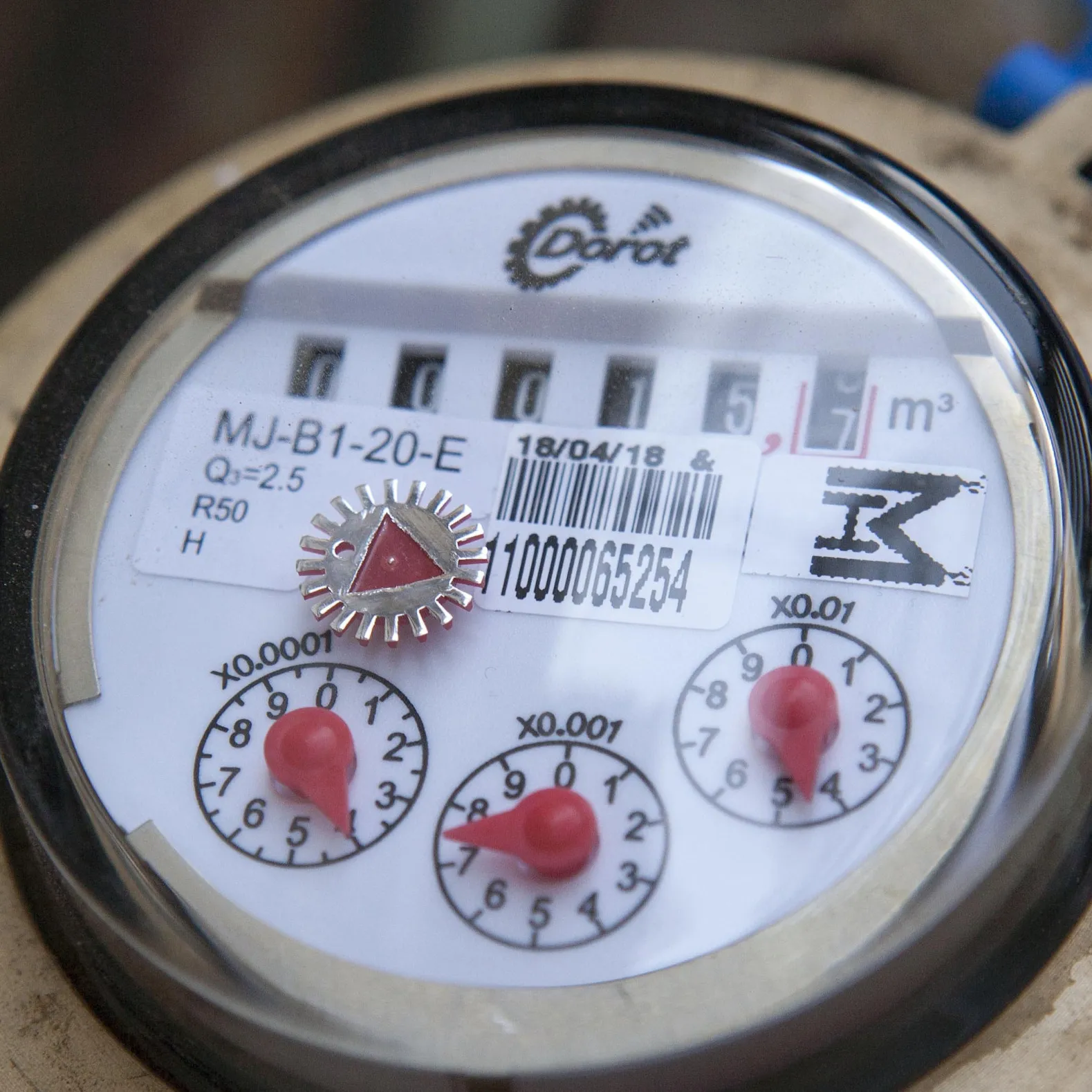
Looking online I found that these types of meters have their AMR transmitter embedded as a part of the mechanical meter itself, housed in the same casing. This was the same company that made the earlier transmitters, partnering up with a company that makes these water meters.
I Asked the vendor for some information, the only data I received that it is still possible to trigger a transmission with a magnet, and it's virtually the same solution (Hint: it's not).
Also, whenever it was "Shabbat" one could see a blinking LED from the housing of the meter, I guess stating that the meter has entered Shabbat mode and it's Kosher so turning on the home faucet, won't violate the Shabbat, to the ones which this is important to them.
I Could also find documentation regarding that this meter is "Kosher" from The Technological Institute of Halacha (הלכה) explaining this feature.
Getting techy: V2 Meters (new, embedded, 4FSK)
Recording
I've tried using the magnets that I have - but this proved not to work, Couldn't find how to trigger it, I Eventually opted for a stronger magnet and found where it needed to be placed in order for it to trigger. When it does, LED turns on for a few seconds.
Tried the frequency I know from the earlier generation - Nothing. I Asked them for the frequency and they responded with 465Mhz, But I Couldn't see any traffic corresponds with my triggering. It seems like they were off in their frequency?
I've again scoured the 300-400 range manually, painfully, slowly. and found that something happens around 433Mhz.
Analysis:
This is how it looked after one trigger, in an amplitude-view
And this is how it looked on a frequency view/waterfall (time:x freq: y)
OMG! Are they using some kind of Frequency Hopping Spread Spectrum? I Wondered... This would be harder then I thought.
______________
Let's anyway try to take a look inside one of these, Now since Universal Radio Hacker is available (as this wasn't available at my first research into the older meters), it made this analysis INSANLY easier. This is after some filtering, and zooming in the signal
At first, this looked strange to me, a digital signal shouldn't look like that. I Also saw these signals around the 465Mhz in my home area (not directly triggering the meter) and at the beginning thought they are some noisy signals.
These signals just captured in my area on 465.65 Mhz seem to match to what I'd expect from such transmission:
- Short, narrow bursts
- Varying degree of quality and noise
- Varying degree of RSSI (i.e. stronger (closer) and weaker (further away) signals, as these meters are all over the place.
Looking online for FHSS information, It looks like synchronization pattern should not appear on each of the channels. also there's quite a delay between the different burst.
In addition to that, the spontaneous transmission on the frequency I received from the vendor did not contain this pattern.
When digging for information about the device, I also saw one of the commercial names for the device. So after a lot of effort googling and researching whatever I can find online I found
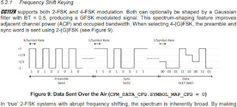
this ! and it did made some sense. This is a 4FSK signal!
I Have tried to see how can I get all the channels back to baseband, thinking I probably need the information which is spread out over the different channels. That was time consuming to do in a pipeline manner, but let's test my theory with the minimal effort needed, does this signal make any sense? what does it mean? can I even start to analyze the data inside using the different meters/different bursts? as a foothold for understanding the traffic?
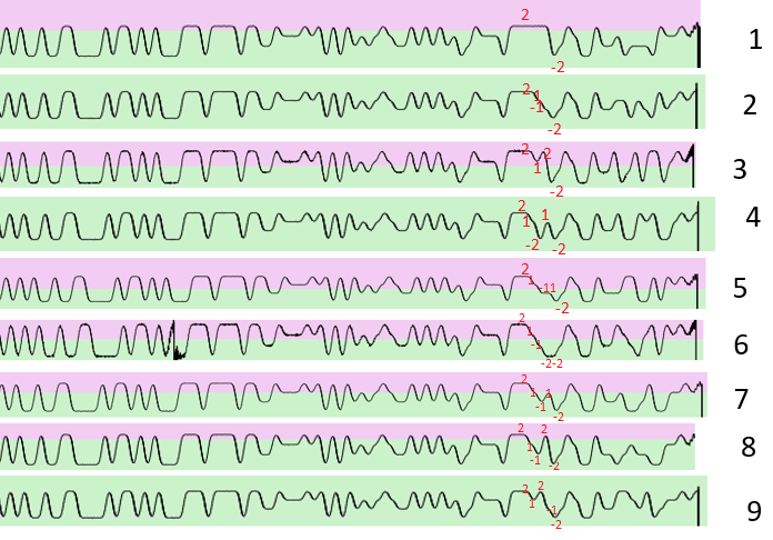
Let's "eyeball" if the data is similar/different within these multiple bursts.
I took each one of these bursts and switched to a frequency view after filtering. I also tried to align the different burst so I can see if there is any meaning
I tried to manually align and compare the different burst and also map where are also the same and where do they divert from each-other
All of these samples were taken from 1 meter in 1 specific occurrence when I triggered the meter only once When water did not flow through it, So information should relatively stay static.
We might expect to see in the transmission values such as:
- Sender or meter identifier - no change
- As demonstrated in 1st generation of the meter, Send counter - not sure, is this one transmission or multiple ones? - if multiple, so we'd expect for each burst bo be +1 from the last one
- Water reading - no change
- Time? - if exists depending on the resolution and the specific capture time
- Checksum - It's a wireless protocol, there is probably some kind of error correction/detection mechanism. Checksum or a CRC would expect to change noticeably if the underlying data is changed (such as the parameters above).
So what do we see here, mostly the same symbols, somewhat a bit different in the middle and in the end there are more changes.
I Manually demodulated the waveform into the 4 different symbols (On the rf spectrum I used 3 1 -1 -3; And on the symbol mapping into bits I've used ABCD as I didn't want to hint myself that A was necessarily 11 etc) and compared each consecutive ones.
The first symbols that is changing across all of the transmission I identified, changes with every transmission (the unmarked one ~mid transmission). there also multiple symbols that change nearer the end of the burst, leave that for now, let's stick to the simple one.
So what if it's a counter that is +1 in each of the bursts? what would we expect to see without any knowledge of the encoding or symbol in such case?
Since it's a 4 fsk signal, each symbol represents 2 bits. so 1 symbol (Symbol `0`) can be the value from 0-3, Where after 3, the higher-value symbol should flip also (Symbol `1`) .
Luckily, we see just this behavior. We don't know exactly in which value do we start on (0-3) but we would expect for the higher-order symbol 1 to change every 4 bursts, and then necessarily 4 more changes to the lower-value symbol before higher symbol changes again. (Also applies 4^2 for flips between symbol [2] and symbol [3]).
If this is too confusing, just think about it as a counter with 2 digits on base 4; but let's look at this base with Alphanumeric chars. A counter would be for example AA AB AC AD BA BB BC BD... etc
If we don't know which of the 2 are the lower value - we could tell by that that it's the one that changes more frequent. In addition, to know what is the lowest value among a set of symbols (i.e. what can be considered a value of 0) we can check if we see 2 simultaneous changes within this counter as the higher value would increment by 1 and the lower value would "zero out",
So, after symbol [0](lower value) and symbols [1](higher value) both flips, we can assume that symbol [0] conveys the value "00". And so we have the symbol mapping. I did this process for also the higher symbol, symbol [1]. And it seems like there is also a 3rd symbol for the counter, but that requires 64 bursts in order to see, which is cumbersome...
So now I have the mapping table for 2 out of, possibly 4 variations of translation.
I wrote multiple scripts of trying to brute force the other patterns, but I could still not find my meter id in the result or have something that makes sense counter-wise.
is the data encoded or encrypted in some other way?
"Remote" Hardware reverse-engineering
After failing to understand the modulation, or at least the translation of the symbols into bits (which may also be not possible, if this data is encrypted). I've tried turning to other ways (again) what is being used to transmit this data, also, why it starts of with a symbols -3,+3 that looks like 2-fsk and only in some point of the transmission goes to "real" 4-level fsk?
I cannot tear down the hardware, but I do have the fcc documentation.
Which chip is being used to transmit this?
Fuzzy photos of the rf chip from the fcc documentation
We know
* Frequency ("sub ghz")
* Symbol rate (Hence, also baud-rate)
* Modulation
* Possibly, preamble and sync pattern
* Packaging of the IC can be extrapolated by the pictures of the PCB, from the pictures in the FCC docs
* Low power
* Narrow-band (where bit rate>=bandwidth, in other words "more frequency changes is compressed into a narrow-er rf spectrum; Like recording LP on a video cassette )
I Have reduced the number of options to 2 vendors, Analog Devices ICs and Texas Instrument ICs judging by this christianistic alongside the number of pins I counted from the ICs photo.
Now, if we were to assume both preamble and sync pattern are 2fsk in this part, preamble would value would be `101010...10` sync would be around 32 bits I counted manually. I decoded the values assuming -3 as 0 and 3 as 1. into Binary: 10010011000010110101000111011110; Hex(First bit received MSB) 93 0b 51 de (0x930b51de).
This wasn't on first shot, I wasn't sure about the size of the preamble and the sync byte, but assuming preamble is repetitive and sync does not contain +1 -1 symbols and should conform to some round-binary number so margin is not to big to look all possible combinations online for the sync word.
Guess what I've found, the sync word maps to multiple example codes online, for Texas Instruments family of transmitters. A special candidate was the CC1120; which
Datasheet say "1.2 Applications: ... Wireless Metering and Wireless Smart Grid (AMR and AMI)" -
Jackpot :)
Drilling further into the
CC112x User guide proved my observations correct. in 4-fsk mode, the preamble and sync word pretend to be 2fsk (I.E. No +1 -1 symbols, only -3 +3). Following sync, transmission moves over to the packet payload part which is 4-fsk.
Symbol mapping
Now we have a bit more clarity of what we're doing and that I'm on the right path.
What are the symbols inside this data map into? The datasheet states there is no "data dependent mapping", They have just all 4 possible combinations
This is where a long guessing game started, it took quite a while, I even thought the information is cyclic-encrypted with a 4 symbol key, or something. but after writing some scripts that would do some brute-forcing I couldn't find anything that made sense.
Universal Radio Hacker to the rescue again!
In one moment, I remembered when looking into URH they have an internal Decoding tool in there was something I recalled to be related to CCxxxx something.
This is basically boils done to XORing the underlying data with a predefined key the CC1120 also supports this feature.
The data and example in the following step might be somewhat wrong or misleading, the research was done a long time ago and I'm just now writing this blog post. The steps and concept mentioned were used in this research just not necessarily the specific data that I'm writing here or the order of the things I've attempted
First I tried using Universal Radio Hacker to extract the data, but that never worked reliably, as each of the transmitter has a slight CFO, URH does not account for that; Also even after re-centering for one specific meter I could never get a reliable slicing of the bits.
I successfully made a GRC flowgraph that was able to extract the symbols from just one capture of one meter that was captured with a magnet, assumed that the mapping is the first one in the datasheet. and extracted the part that comes just after the preamble:
F0 EA ~~ DA 8B 83 833324EA7F51 (some data censored with ~)
For data whitening the key starts with FFE11F9AED853324EA...
When decoded it looks something like this:
0F 0B ~~ 40 66 06 000000...xxxx
- So again - looks like we're on the right path! all of these different symbols, when XORed with the right value, zeroes out if were to do just random XOR or something that wouldn't make sense, what are the chances of the data accidently zeroing out?.
Now, with a little bit of trial and error I've reached to a conclusion that xxxx is a checksum of all the information before that. Why I tried that? well look in the photos above of multiple such transmissions visible and aligned together. It's possible that a "slight" change in the payload, would lead to a big change in the checksum (which is presumed to be near the end). This hits us that the last part of the transmission is a checksum of some sort.
The meaning of life (ahh.. data)
Now we have what looks like demodulated, decoded, unencrypted data.
We need to start actually understanding it.
This is where I thought the knowledge from the
old gen meters would help - Totally didn't, trying out both manually and the excel method didn't yield anything; As with the previous generation. I expected to see the meter id in the transmission - But failed time after time.
I totally missed that, but can you see a hint in this picture for the way data is encoded into the payload?
Assuming u did missed that, as I did too, eventually I accidently decoded the different bytes into decimal, instead of hex.
Suddenly sublime highlighted me the top-value of the meter id within the same file matches the payload.
I call it "decimally-numerically encoded"! hell - Who thought of this grate idea?
... And please let's never hear this term again...
What's that - It's like BCD coding for 3 decimal digits into a byte value, you can represent 3 10-base digits as long as they're value don't go above 255, this is why you will never find a meter id ending with higher then xxxxxxx255 ! (also applies for higher tribbles ("three nibbles")).
This was later a straightforward process the packet recorded in the magnet proved to contain, only, length, meter id along with an additional unknown byte, lots of zeros and a checksum.
Going municipal
Well there is no other data to analyze in the frame recorded in the magnet. So I switched over to the other frequency (465mhz) to try to pick up the neighborhood meters.
I had lots of bad frames, by this can be verified by a checksum so I don't need to guess which ones were received and parsed correctly.
in the wild, we have several sizes of frames, they aren't always this small.
Applying what I've learned above to the framed received correctly worked I could see the transmitting meter Id; but the Id also appeared, sometimes in a frame following it, in a different location.
Judging that that the received RSSI was different, I was thinking this is a 2 way system, where the meter sends data to the base station and the base station returns data to the meter (most of the time, something like a timestamp). Awesome.
I Have used a setup with an SDR connected to a DVB-T Antenna on top of my building - which basically say, yes, I can receive lots of the area.
From here this was fairly easy but long iterative process, where I was able to understand the meaning of the data in this different frame types as expressed in the python code in the github repository.
Conclusion
* OMG - That worked!
* Hell - It took ages to figure everything out
* When writing on this in this blog post, everything seems fast and efficient; That's not the case, sometime there was no any progress for weeks. Recording in the residential area with the rooftop antenna needed to occur overnight as I'm looking for specific meters and they rarely transmit. overall I'd estimate this took me around 1 year overall (off course I sometime have life, family and job as well so consider that)
* Some thigs are still technical issues:
* I Don't actually know how to demodulate 4-fsk, I tried lots of different things until something worked, 60% of the received transmissions. - Please consider contributing to the repository if u know anything in SDR :)
* It's not really clear why the with a magnet, the transmitter sends data on 433mhz instead of it's original frequency.


No comments:
Post a Comment